|
APLAC Models are available for the following PIN diodes. SPICE models are not available for Agilent Technologies PIN diodes as SPICE does not model carrier lifetime, a critical parameter for PIN diodes.
APLAC Limited PIN Diode Model
The APLAC model predicts the RF resistance of a PIN diode chip under all bias conditions, and is based on the article
SPICE CIRCUIT YIELDS RECIPE FOR PIN DIODE, Joe Walston, Microwaves & RF - November 1992.
APLAC MODEL LIMITATIONS:
 |
- The model can be used to predict the r.f. resistance and forward voltage. It does not give predictions of distortion.
- A PIN diode only behaves reliably as a variable resistor at frequencies above 10fc, where fc = 1/2pt and t is the minority carrier lifetime.
- The capacitance of a PIN diode does vary with the reverse voltage applied however the APLAC model only allows a fixed value.
- APLAC uses carrier lifetime (t) as an approximation for transit time (TT).
|
HSMP-380x Limited APLAC Model
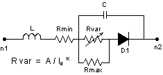
D1 uses the standard SPICE diode model, and is described by Is, N, and TT. Rs in the standard model is replaced by the external network
of Rmin, Rmax, and Rvar. The parameters are for a single diode (HSMP-3800). Parameters also apply to the individual diodes within multiple
diode configurations.
| parameter | units | description | value |
| Rmax | ohm | maximum r.f. resistance | 10000 |
| Rmin | ohm | minimum r.f. resistance | 2 |
| K | - | resistance curve fitting exponent | 1.015 |
| A | - | resistance curve fitting constant | 0.0434 |
| L | nH | connection inductance | 2 |
| C | pF | diode capacitance at r.f. frequency | 0.3 |
| Is | A | diode saturation current | 3.5E-9 |
| N | - | diode ideality factor | 2.062 |
| TT | nsec | transit time (carrier lifetime) | 1800 |
APLAC Limited PIN Diode Model
The APLAC model predicts the RF resistance of a PIN diode chip under all bias conditions, and is based on the article
SPICE CIRCUIT YIELDS RECIPE FOR PIN DIODE, Joe Walston, Microwaves & RF - November 1992.
APLAC MODEL LIMITATIONS:
|
- The model can be used to predict the r.f. resistance and forward voltage. It does not give predictions of distortion.
- A PIN diode only behaves reliably as a variable resistor at frequencies above 10fc, where fc = 1/2pt and t is the minority carrier lifetime.
- The capacitance of a PIN diode does vary with the reverse voltage applied however the APLAC model only allows a fixed value.
- APLAC uses carrier lifetime (t) as an approximation for transit time (TT).
|
HSMP-381x Limited APLAC Model
D1 uses the standard SPICE diode model, and is described by Is, N, and TT. Rs in the standard model is replaced by the external network
of Rmin, Rmax, and Rvar. The parameters are for a single diode (HSMP-3800). Parameters also apply to the individual diodes within multiple
diode configurations.
| parameter | units | description | value |
| Rmax | ohm | maximum r.f. resistance | 12000 |
| Rmin | ohm | minimum r.f. resistance | 2.5 |
| K | - | resistance curve fitting exponent | 0.987 |
| A | - | resistance curve fitting constant | 0.0902 |
| L | nH | connection inductance | 2 |
| C | pF | diode capacitance at r.f. frequency | 0.25 |
| Is | A | diode saturation current | 1.2E-9 |
| N | - | diode ideality factor | 1.998 |
| TT | nsec | transit time (carrier lifetime) | 1500 |
APLAC Limited PIN Diode Model
The APLAC model predicts the RF resistance of a PIN diode chip under all bias conditions, and is based on the article
SPICE CIRCUIT YIELDS RECIPE FOR PIN DIODE, Joe Walston, Microwaves & RF - November 1992.
APLAC MODEL LIMITATIONS:
|
- The model can be used to predict the r.f. resistance and forward voltage. It does not give predictions of distortion.
- A PIN diode only behaves reliably as a variable resistor at frequencies above 10fc, where fc = 1/2pt and t is the minority carrier lifetime.
- The capacitance of a PIN diode does vary with the reverse voltage applied however the APLAC model only allows a fixed value.
- APLAC uses carrier lifetime (t) as an approximation for transit time (TT).
|
HSMP-382x Limited APLAC Model
D1 uses the standard SPICE diode model, and is described by Is, N, and TT. Rs in the standard model is replaced by the external network
of Rmin, Rmax, and Rvar. The parameters are for a single diode (HSMP-3800). Parameters also apply to the individual diodes within multiple
diode configurations.
| parameter | units | description | value |
| Rmax | ohm | maximum r.f. resistance | 5000 |
| Rmin | ohm | minimum r.f. resistance | 0.35 |
| K | - | resistance curve fitting exponent | 0.767 |
| A | - | resistance curve fitting constant | 0.00825 |
| L | nH | connection inductance | 2 |
| C | pF | diode capacitance at r.f. frequency | 0.8 |
| Is | A | diode saturation current | 1.15E-11 |
| N | - | diode ideality factor | 1.641 |
| TT | nsec | transit time (carrier lifetime) | 70 |
APLAC Limited PIN Diode Model
The APLAC model predicts the RF resistance of a PIN diode chip under all bias conditions, and is based on the article
SPICE CIRCUIT YIELDS RECIPE FOR PIN DIODE, Joe Walston, Microwaves & RF - November 1992.
APLAC MODEL LIMITATIONS:
|
- The model can be used to predict the r.f. resistance and forward voltage. It does not give predictions of distortion.
- A PIN diode only behaves reliably as a variable resistor at frequencies above 10fc, where fc = 1/2pt and t is the minority carrier lifetime.
- The capacitance of a PIN diode does vary with the reverse voltage applied however the APLAC model only allows a fixed value.
- APLAC uses carrier lifetime (t) as an approximation for transit time (TT).
|
HSMP-383x Limited APLAC Model
D1 uses the standard SPICE diode model, and is described by Is, N, and TT. Rs in the standard model is replaced by the external network
of Rmin, Rmax, and Rvar. The parameters are for a single diode (HSMP-3800). Parameters also apply to the individual diodes within multiple
diode configurations.
| parameter | units | description | value |
| Rmax | ohm | maximum r.f. resistance | 5000 |
| Rmin | ohm | minimum r.f. resistance | 1.5 |
| K | - | resistance curve fitting exponent | 0.9327 |
| A | - | resistance curve fitting constant | 0.0183 |
| L | nH | connection inductance | 2 |
| C | pF | diode capacitance at r.f. frequency | 0.2 |
| Is | A | diode saturation current | 1.49E-9 |
| N | - | diode ideality factor | 2.022 |
| TT | nsec | transit time (carrier lifetime) | 500 |
APLAC Limited PIN Diode Model
The APLAC model predicts the RF resistance of a PIN diode chip under all bias conditions, and is based on the article
SPICE CIRCUIT YIELDS RECIPE FOR PIN DIODE, Joe Walston, Microwaves & RF - November 1992.
APLAC MODEL LIMITATIONS:
|
- The model can be used to predict the r.f. resistance and forward voltage. It does not give predictions of distortion.
- A PIN diode only behaves reliably as a variable resistor at frequencies above 10fc, where fc = 1/2pt and t is the minority carrier lifetime.
- The capacitance of a PIN diode does vary with the reverse voltage applied however the APLAC model only allows a fixed value.
- APLAC uses carrier lifetime (t) as an approximation for transit time (TT).
|
HSMP-386x Limited APLAC Model
D1 uses the standard SPICE diode model, and is described by Is, N, and TT. Rs in the standard model is replaced by the external network
of Rmin, Rmax, and Rvar. The parameters are for a single diode (HSMP-3800). Parameters also apply to the individual diodes within multiple
diode configurations.
| parameter | units | description | value |
| Rmax | ohm | maximum r.f. resistance | 5000 |
| Rmin | ohm | minimum r.f. resistance | 1.5 |
| K | - | resistance curve fitting exponent | 0.9327 |
| A | - | resistance curve fitting constant | 0.0183 |
| L | nH | connection inductance | 2 |
| C | pF | diode capacitance at r.f. frequency | 0.2 |
| Is | A | diode saturation current | 1.49E-9 |
| N | - | diode ideality factor | 2.022 |
| TT | nsec | transit time (carrier lifetime) | 500 |
APLAC Limited PIN Diode Model
The APLAC model predicts the RF resistance of a PIN diode chip under all bias conditions, and is based on the article
SPICE CIRCUIT YIELDS RECIPE FOR PIN DIODE, Joe Walston, Microwaves & RF - November 1992.
APLAC MODEL LIMITATIONS:
|
- The model can be used to predict the r.f. resistance and forward voltage. It does not give predictions of distortion.
- A PIN diode only behaves reliably as a variable resistor at frequencies above 10fc, where fc = 1/2pt and t is the minority carrier lifetime.
- The capacitance of a PIN diode does vary with the reverse voltage applied however the APLAC model only allows a fixed value.
- APLAC uses carrier lifetime (t) as an approximation for transit time (TT).
|
HSMP-388x Limited APLAC Model
D1 uses the standard SPICE diode model, and is described by Is, N, and TT. Rs in the standard model is replaced by the external network
of Rmin, Rmax, and Rvar. The parameters are for a single diode (HSMP-3800). Parameters also apply to the individual diodes within multiple
diode configurations.
| parameter | units | description | value |
| Rmax | ohm | maximum r.f. resistance | 5000 |
| Rmin | ohm | minimum r.f. resistance | 1 |
| K | - | resistance curve fitting exponent | 0.864 |
| A | - | resistance curve fitting constant | 0.0486 |
| L | nH | connection inductance | 2 |
| C | pF | diode capacitance at r.f. frequency | 0.4 |
| Is | A | diode saturation current | 1.49E-9 |
| N | - | diode ideality factor | 1.947 |
| TT | nsec | transit time (carrier lifetime) | 2500 |
APLAC Limited PIN Diode Model
The APLAC model predicts the RF resistance of a PIN diode chip under all bias conditions, and is based on the article
SPICE CIRCUIT YIELDS RECIPE FOR PIN DIODE, Joe Walston, Microwaves & RF - November 1992.
APLAC MODEL LIMITATIONS:
|
- The model can be used to predict the r.f. resistance and forward voltage. It does not give predictions of distortion.
- A PIN diode only behaves reliably as a variable resistor at frequencies above 10fc, where fc = 1/2pt and t is the minority carrier lifetime.
- The capacitance of a PIN diode does vary with the reverse voltage applied however the APLAC model only allows a fixed value.
- APLAC uses carrier lifetime (t) as an approximation for transit time (TT).
|
HSMP-389x Limited APLAC Model
D1 uses the standard SPICE diode model, and is described by Is, N, and TT. Rs in the standard model is replaced by the external network
of Rmin, Rmax, and Rvar. The parameters are for a single diode (HSMP-3800). Parameters also apply to the individual diodes within multiple
diode configurations.
| parameter | units | description | value |
| Rmax | ohm | maximum r.f. resistance | 5000 |
| Rmin | ohm | minimum r.f. resistance | 0.5 |
| K | - | resistance curve fitting exponent | 0.746 |
| A | - | resistance curve fitting constant | 0.0202 |
| L | nH | connection inductance | 2 |
| C | pF | diode capacitance at r.f. frequency | 0.2 |
| Is | A | diode saturation current | 1.68E-11 |
| N | - | diode ideality factor | 1.673 |
| TT | nsec | transit time (carrier lifetime) | 200 |
|